As already described before, the most used flange types ASME B16.5 are.. Welding Neck, Slip On, Socket Weld, Lap Joint, Threaded and Blind flange. Below you will find a short description and definition of each type, completed with an detailed image.
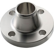
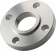
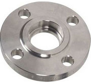
Welding Neck flange Slip On flange Socket Weld flange
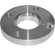
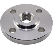
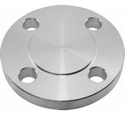
Lap Joint flange Threaded flange Blind flange
All types except the Lap Joint flange are provided with a raised flange face.
Welding Neck flange
Welding Neck Flanges are easy to recognize at the long tapered hub, that goes gradually over to the wall thickness from a pipe or fitting.
The long tapered hub provides an important reinforcement for use in several applications involving high pressure, sub-zero and / or elevated temperatures. The smooth transition from flange thickness to pipe or fitting wall thickness effected by the taper is extremely beneficial, under conditions of repeated bending, caused by line expansion or other variable forces.
These flanges are bored to match the inside diameter of the mating pipe or fitting so there will be no restriction of product flow. This prevents turbulence at the joint and reduces erosion. They also provide excellent stress distribution through the tapered hub and are easily radiographed for flaw detection.
This flange type will be welded to a pipe or fitting with a single full penetration, V weld (Buttweld).
Details of Welding Neck flange
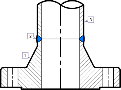
1.Weld Neck flange 2.Butt Weld 3.Pipe or Fitting
Slip On flange
The calculated strength from a Slip On flange under internal pressure is of the order of two-thirds that of Welding Neck flanges, and their life under fatigue is about one-third that of the latter.
The connection with the pipe is done with 2 fillet welds, as well at the outside as also at the inside of the flange.
The X measure on the image, are approximately..
Wall thickness of pipe + 3 mm.
This space is necessary, to do not damage the flange face, during the welding process.
A disadvantage of the flange is, that principle always firstly a pipe must be welded and then just a fitting. A combination of flange and elbow or flange and tee is not possible, because named fittings have not a straight end, that complete slid in the Slip On flange.
Details of Slip On flange
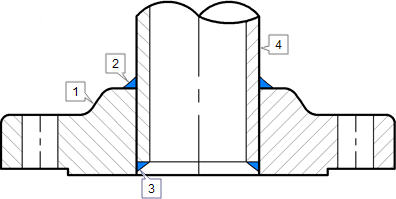
1.Slip On flange 2.Filled weld outside 3.Filled weld inside 4.Pipe
Socket Weld flange
Socket Weld flanges were initially developed for use on small-size high pressure piping. Their static strength is equal to Slip On flanges, but their fatigue strength 50% greater than double-welded Slip On flanges.
The connection with the pipe is done with 1 fillet weld, at the outside of the flange. But before welding, a space must be created between flange or fitting and pipe.
ASME B31.1 1998 127.3 Preparation for Welding (E) Socket Weld Assembly says..
In assembly of the joint before welding, the pipe or tube shall be inserted into the socket to the maximum depth and then withdrawn approximately 1/16″ (1.6 mm) away from contact between the end of the pipe and the shoulder of the socket.
The purpose for the bottoming clearance in a Socket Weld is usually to reduce the residual stress at the root of the weld that could occur during solidification of the weld metal. The image shows you the X measure for the expansion gap.
The disadvantage of this flange is right the gap, that must be made. By corrosive products, and mainly in stainless steel pipe systems, the crack between pipe and flange can give corrosion problems. In some processes this flange is also not allowed. I am not an expert in this matter, but on the internet, you will find a lot of information about forms of corrosion.
Also for this flange counts, that principle always firstly a pipe must be welded and then just a fitting.
Details of Socket Weld Flange
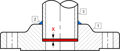
1.Socket Weld flange 2.Filled weld 3.Pipe X = Expansion gap
Lap Joint flange
Lap Joint Flanges have all the same common dimensions as any other flange named on this page however it does not have a raised face, they used in conjunction with a “Lap Joint Stub End”.
These flanges are nearly identical to a Slip On flange with the exception of a radius at the intersection of the flange face and the bore to accommodate the flanged portion of the Stub End.
Their pressure-holding ability is little, if any, better than that of Slip On flanges and the fatigue life for the assembly is only one tenth that of Welding Neck flanges.
They may be used at all pressures and are available in a full size range. These flanges slip over the pipe, and are not welded or otherwise fastened to it. Bolting pressure is transmitted to the gasket by the pressure of the flange against the back of the pipe lap (Stub End).
Lap Joint flanges have certain special advantages..
- Freedom to swivel around the pipe facilitates the lining up of opposing flange bolt holes.
- Lack of contact with the fluid in the pipe often permits the use of inexpensive carbon steel flanges with corrosion resistant pipe.
- In systems which erode or corrode quickly, the flanges may be salvaged for re-use.
Details of Lap Joint Flange
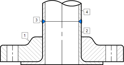
1.Lap Joint flange 2.Stub End 3.Butt weld 4.Pipe or Fitting Stub End
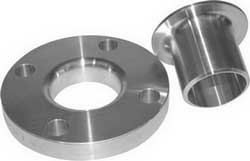
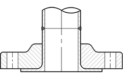
A Stub End always will be used with a Lap Joint flange, as a backing flange.
This flange connections are applied, in low-pressure and non critical applications, and is a cheap method of flanging.
In a stainless steel pipe system, for example, a carbon steel flange can be applied, because they are not come in contact with the product in the pipe.
Stub Ends are available in almost all pipe diameters. Dimensions and dimensional tolerances are defined in the ASME B.16.9 standard. Light-weight corrosion resistant Stub Ends (fittings) are defined in MSS SP43.
Lap Joint Flange with a Stub End
Threaded flange
Threaded Flanges are used for special circumstances with their main advantage being that they can be attached to the pipe without welding. Sometimes a seal weld is also used in conjunction with the threaded connection.
Although still available in most sizes and pressure ratings, screwed fittings today are used almost exclusively in smaller pipe sizes.
A threaded flange or fitting is not suitable for a pipe system with thin wall thickness, because cutting thread on a pipe is not possible. Thus, thicker wall thickness must be chosen…what is thicker ?
ASME B31.3 Piping Guide says..
Where steel pipe is threaded and used for steam service above 250 psi or for water service above 100 psi with water temperatures above 220° F, the pipe shall be seamless and have a thickness at least equal to schedule 80 of ASME B36.10.
Details of Threaded flange
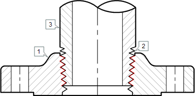
1.Threaded flange 2.Thread 3.Pipe or Fitting
Blind flange
Blind Flanges are manufactured without a bore and used to blank off the ends of piping, Valves and pressure vessel openings.
From the standpoint of internal pressure and bolt loading, blind flanges, particularly in the larger sizes, are the most highly stressed flange types.
However, most of these stresses are bending types near the center, and since there is no standard inside diameter, these flanges are suitable for higher pressure temperature applications.
Details of Blind flange
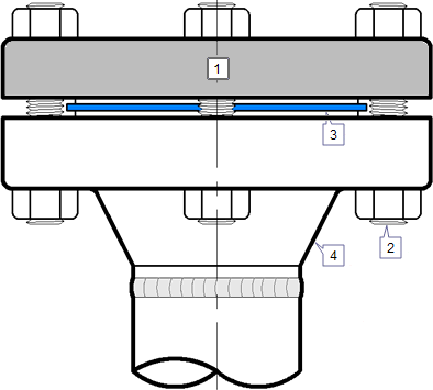
1.Blind flange 2.Stud Bolt 3.Gasket 4.Other flange

